First Homemade Nearing Completion

Homemade water gun threads that are notable.
User avatar
Drenchenator
Posts: 807
Joined: Fri Jun 18, 2004 12:00 pm

First Homemade Nearing Completion

Post by Drenchenator » Sun Aug 06, 2006 12:31 am

I have been working slowly and steadily for the past two weeks on my first homemade water gun. I am really excited that this gun is almost finished because I want it to be my main weapon in an upcoming water war. It has a completely innovative and practical design. Normally I don't like to post previews or things like this, but the gun is technically operational, so I will let it slide. This gun is not completely finished. The case needs to be completed (on the top), the trigger needs to be "recalibrated", the trigger system needs to move more smoothly (it rubs against the PVC), and the handle needs to be installed. Nevertheless, it can shoot water.

Image

I haven't named this soaker yet, but I have been thinking of some good names. It is basically your standard CPS gun only made from PVC and steel piping. And just like every other standard CPS gun, it has a trigger. The gun does not have the handle attached yet, so the handle-like thing is actually the trigger (the handle is the pipe in the foreground. Currently the pressure chamber is the old worn out chamber from Ben's CPS homemade, but once I finish the gun I will replace it with some brand new latex rubber tubing.

Image

This gun is actually pretty small, especially considering that it is a homemade. It is only 24 inches long and when completed with a bladder casing only about 6 inches tall (not counting the handle of course). There it is, next to an XP 150, just slightly larger. The gun is rather heavy though. Currently it is 5 pounds without any water in it, but this is from the steel piping in it (steel is very heavy). It is well balanced though.

Image

The trigger valve is simply a 1/2" brass ball valve with a new replacement torque arm. The torque arm took a long time to make. In fact, it took me 3 designs to come up with a good one. The new torque arm was cut out with a dremel. The holes were drilled with a small drill press and then I bend it into shape with a hammer.

The trigger does activate the ball valve, but at the moment only opens the valve about three quarters of the way. This creates a ton of turbulence because it ruins the linear flow. I just have to make the trigger pull larger to fix this because I can't decrease the torque arm length anymore (I drilled two holes in the new torque arm, and the one closer to the nut needs less of a trigger pull to activate the valve all the way). The valve also lacks a return feature, but I will add one once the case is completed (it needs something to attach too). But it is functional, just not optimally functional.

Image

The pump is connected to the trigger valve by use of 3/8" vinyl tubing. This allows each part of the gun to be completely replaceable and upgradeable. If you want a larger pump, you can replace the old pump with a new one easily. The gun is held together by nuts and bolts. Currently, only two bolts hold the two sections together, but I will hopefully add up to four for redundancy. It is held together well by two, but more will not hurt.

Image

I hope to complete this gun within a week. Please post comments and such, I really have worked hard to make a great homemade and would like some feedback.
Last edited by Drenchenator on Wed Jan 16, 2008 10:42 pm, edited 1 time in total.
The Drenchenator, also known as Lt. Col. Drench.

User avatar
Silence
Posts: 3825
Joined: Sun Apr 09, 2006 9:01 pm

Post by Silence » Sun Aug 06, 2006 3:56 am

I'm only too happy to be the first to commend you for your effort on this soaker! I've judged that you're extremely thorough and meticulous--I first "suspected" that with your Nerf homemade, and this pretty much clinched it. Plus, I can actually appreciate the technology behind this since it has to do with water guns.

That's a very well done homemade--both in functionality and in looks. At first glance, the design of the trigger system is very different from what I have in mind, but now I see that it is very similar. Pretty much all that's different is that the trigger is positioned below the valve (something I had never thought of, but now I'll keep it in mind) and the wire-attaching piece is custom (I would have used PVC). My method would have been very sloppy while getting the job done, but the time and skill required for this are tremendous. I'll just have to live up to this standard...

Why did you use pipe nipples and metal fittings for part of the design? Unless you're using pressures far beyond what's reasonable, it just seems to add weight. That said, there are a few places I would use metal: in check valves for designs that call for small ones, and possibly in ball valves if I'm doing something like what you just did.

I'm assuming the reason your "trigger" can't open the trigger valve all the way is because of the positioning of the ball valve's new "handle." At the end of the current trigger pull, the handle points toward the trigger--which means you can't turn it any more, as vector force when you pull the trigger is in the direction of the handle! Perhaps better physics knowledge would aid my terminology, but I think you get the idea. My suggestion is pretty much to reorient the handle (if possible) so that it starts off pointing 10 or 15 degrees more towards the front of the soaker.

But you say that the trigger problem stems from the fact that the wire is attached too close to the ball valve screw. Could you explain why this is? If the problem is related to what I said in the above paragraph, then perhaps that would work.

The trigger is positioned fairly far forward on the soaker, but if it's still balanced as you say where the handle should be, I suppose that isn't too bad (also, it keeps the pump close to the handle). By the way, what lies in the back part of the tubing? I doubt the pump tube reaches that far back, but still...the soaker would be even shorter if not for it, but I'm sure it's there for a purpose. Actually, the soaker would be nearly as short as my compact APH if you increased my APH's pump past its measly 6 inches...

Anyway, good luck with the completion of this soaker! I'm looking forward to stats when you get the new LRT... :cool:

User avatar
m15399
Posts: 224
Joined: Sat Oct 15, 2005 1:54 am

Post by m15399 » Sun Aug 06, 2006 6:23 am

Awesome!

How much resistance to you get from the trigger? It seems like since it is connected to the valve so close to its pivot point that it would require a great deal of force to turn it.

Do you think a homemade valve would have been a better option?

User avatar
Silence
Posts: 3825
Joined: Sun Apr 09, 2006 9:01 pm

Post by Silence » Sun Aug 06, 2006 12:45 pm

Well, he said he was moving the torque arm attachment point, and anyway it is pulled by the whole hand (I think)...and also, a homemade valve would not have provided laminar flow. You're right though--there are a ton of options if you're not going laminar. You could do a homemade valve like in his Nerf homemade or in that SM thread, a modified solenoid, etc.

User avatar
Drenchenator
Posts: 807
Joined: Fri Jun 18, 2004 12:00 pm

Post by Drenchenator » Sun Aug 06, 2006 2:11 pm

Thanks for all the compliments. I tend to go overboard on the hard work sometimes when I am excited, so this thing is pretty high quality as far as I am concerned. A guide is in the works as well. I have about 180 pictures taken of the construction so far, so this one will be detailed. If anything, people should look at the guide just to see how I build the pump, it is much higher quality that anything else in soakers.
Why did you use pipe nipples and metal fittings for part of the design?
To tell the truth, the only steel fitting is the tee, which is where a lot of the weight comes from. I used metal fittings because I thought that they would be smaller (in length), which is true many times. But they do add a lot of unnecessary weight. I didn't use them because I though there would be a lot of pressure, in fact, I am sure that the bladder would explode before even PVC would. I may "upgrade" the trigger valve later by replacing most of it with PVC, which should reduce the weight a ton.

One note though, on my use of check valves. I tried to only use locally available parts (excluding the tubing of course, which is technically locally available because Ben has some in my house). The shortest check valves that I found were not spring check valves, they were swing check valves. Spring check valves operate by the use of a spring holding shut a door, but swing check valves don't have anything to hold the door shut, except gravity of course. This means that they can't be used in certain circumstances (like upside down mostly). They do decrease the length substancially though. They increase the height as well, but this is no problem because I made it so that they increase the height into "dead space" (where nothing was the 1 1/2" PVC case). Another possible "upgrade" for this gun would be the use of regular run of the mill spring check valves.
But you say that the trigger problem stems from the fact that the wire is attached too close to the ball valve screw. Could you explain why this is? If the problem is related to what I said in the above paragraph, then perhaps that would work.
Actually, I thought that I said that I moved the wire there to reduce the pull needed (not the force, just the length of pull needed). A circle has less circumference when it the radius is smaller, right? So I reduced the radius, which in turn should reduce the distance needed to open the valve (but increase the force).

The problem is actually coming from the friction of the wire against the PVC case and elbow adapter, and from the limitations of what I have built already (the trigger can only go back so far at the moment, put I can increase the pull by increasing the length of "trigger hole".
The trigger is positioned fairly far forward on the soaker, but if it's still balanced as you say where the handle should be, I suppose that isn't too bad (also, it keeps the pump close to the handle).
I have to agree that they are a bit to far forward, but I designed it to be this way. I did some measurements beforehand of where the handle and trigger are in relation to the end of the soaker on the few soakers that I have available (XP 150, CPS 1000, CPS 1200, and CPS 2100). It seems that most grips and handles are about 8 to 9 inches from the end of the soaker, while mine is 10 or 11 inches I believe. It is just a matter of preference I suppose, because the soaker feels fine to me.
By the way, what lies in the back part of the tubing? I doubt the pump tube reaches that far back, but still...the soaker would be even shorter if not for it, but I'm sure it's there for a purpose.
I am surprise that I didn't actually show that part, but I took some pictures that should explain a lot. This soaker is not as complicated as many of you may think, because I designed it to work pretty much like a stock soaker. It was just very complicated to build.

Image

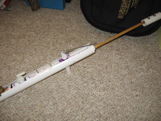
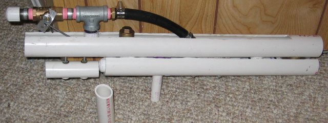
This is the entire "lower layer" of the soaker. It contains the pump and the input check valve. The elbow barb is just the output of the pump, and is easily connected to the trigger valve with a piece of vinyl tubing. The pump has a volume of 60 mL and is 12 inches long.

Image

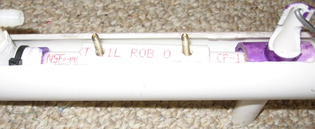
The center of the lower layer contains the most vital structural component. This piece of 1" PVC easily fits over the pump shaft, and allows the four screws to connect the bottom of the lower layer to the center layer easily. This was one of my completely original ideas. It also is the only way that I can see a soaker like this being constructed without "external help" currently, so hopefully someone will take where I left off and build a newer, better system.

The trigger is on the right in that picture (and near the center of the first picture). This trigger system is pretty much a copy of the one used on many CPS soakers. This internals shot of a CPS 2100 should show how. Somehow, I had to get the trigger that is underneath the pump, to pull on a wire over the pump. So, I drilled a 7/8" hole straight through a 2" long of 1" PVC, and cemented a 5.5" piece of 1/2" PVC into it. I then drilled a hole through the center of the 1" pipe, clearing it for the pump to get through. It is just your basic "tracked trigger".

Image

The top of the trigger was cut down to allow the tubing to go by too. Surprisingly, that took me a long time to think of. Originally, I drilled a 1/2" hole in the pipe to allow the tubing to go through. This offered so much resistance that the trigger could barely work. So I made the hole bigger. And bigger. This is until I realized to cut one side off and leave one on. Now it works well.
Actually, the soaker would be nearly as short as my compact APH if you increased my APH's pump past its measly 6 inches...
That's pretty funny, because this thing has a 12 inch pump. I also just noticed that this thing's heavy weight could be due to the density of it. It has a lot of stuff in a very small space.
How much resistance to you get from the trigger? It seems like since it is connected to the valve so close to its pivot point that it would require a great deal of force to turn it.
I actually get a lot of resistance from the trigger. From how close the wire hole is and from the friction of the wire against the casing. I have a lot of work to do, mostly just tinkering with it to slowly fix these problems. The soaker is basically operational, just not optimally.

It does require a lot of force of open the valve. But I am trying to balance opening the valve all the way against comfort, so at the moment I am more concerned with opening the valve all the way. Hopefully once I get that to happen some lubrication will help open the valve easier. Since I am the first one to do this kind of stuff in soakers, I have to settle for functionally over comfort.
Do you think a homemade valve would have been a better option?
Originally, I designed this gun to use a homemade pull valve. Ben brought it up in a Soaker Media topic that I have designed a homemade pull valve using rubber sheeting in early July when I started building this gun. To tell the truth, this design is the redesign of a failed first design using a homemade valve. I removed it for two reasons. The pull valve would not allow linear flow and therefore decrease the laminar flow. The pull valve also would not be repairable and also be a pain to build. This way is not like the one in my Nerf homemade, which is very easy to repair (just remove the piston). This one was a true copy of a standard Super Soaker pull valve, and would have the same problems as them too.

I removed the homemade valve from my plans simply because it would not perform as well. I do have some fairly vague "goals" for this gun, which are pretty much a 50 foot range (easy in homemade guns), and having a huge bladder/chamber capacity. There is a reason that this thing does not have a reservoir, I think that it does not need one! The only "effective" water is the water in the bladder/chamber, so I designed this thing with plenty of space for the bladder. And if worst comes to worst, I can use my SS 300 backpack.

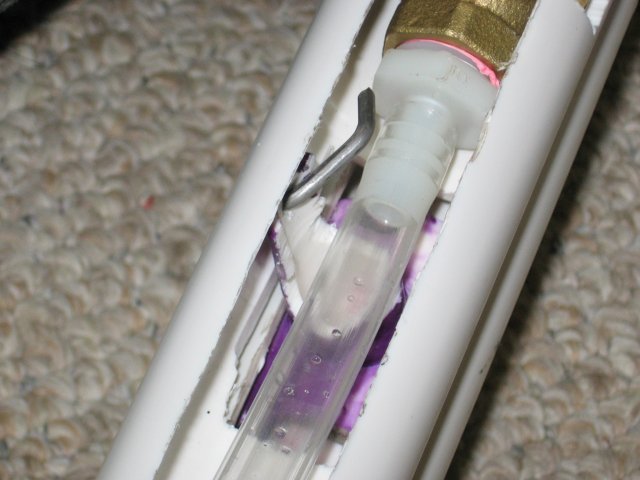
In the redesign, I settled for just a simple brass ball valve. The old saying "Keep It Simple Stupid!" really got me before, so I went for a simple route. The hardest part with using a brass ball valve is the you have to create the new torque are, but once that is done, it is ready to use. And if the valve breaks, you can buy a new one and use the old torque arm. A much simpler repair system.
Last edited by Drenchenator on Wed Jan 16, 2008 10:43 pm, edited 1 time in total.
The Drenchenator, also known as Lt. Col. Drench.

User avatar
Silence
Posts: 3825
Joined: Sun Apr 09, 2006 9:01 pm

Post by Silence » Sun Aug 06, 2006 2:58 pm

Well then, let me congratulate you again. I'm sure you'll get the finer details sorted out at some point, and I think I understand the functionality vs. comfort issue now.

Those pictures truly help me appreciate how high-quality and thorough your work was during construction. Nothing seems out of place, and from the replacement torque arm to the carved trigger attachment point, all the customization make this a refined and commercial-style gun.

I'm assuming you didn't see my last post, but that's because I must have started it after you started yours, looking at the post times. Anyway, good luck with the fine-tuning, and I hope all goes well!

User avatar
Drenchenator
Posts: 807
Joined: Fri Jun 18, 2004 12:00 pm

Post by Drenchenator » Sun Aug 06, 2006 6:12 pm

Well, after some tinkering I found out why the valve is not opening all the way. It seems that there is not only friction between the wire and case, but also between the wire and aluminum torque arm. The arm slides right against the wire after about 1/2 of a turn, preventing the valve from opening further. I discovered this after forcing the valve open by manually turning the torque arm. Five minutes with a hacksaw and file fixed that easily. After some wire adjustments, about 80 to 90 percent of the pull (length) needed is being provided without using a direct method (increasing the pull of the trigger itself).

There is another problem though that I think is preventing the valve from opening all the way. I thought that the trigger assembly itself would be strong because I solvent welded (PVC cemented) it together. But it seems that after I drilled a hole through it, it lost a lot of structural support. The actual trigger part of the assembly is moving slightly, which is not good because all of the force is not being used in opening the valve. So I am going to remake the whole trigger assembly, but this time reinforce the certain areas. Hopefully a rigid trigger would transfer more force to open the valve. This really is not much of a problem considering some of the other pieces that I had to redo (the torque arm 3 times, the lower layer once before with the original design).
Those pictures truly help me appreciate how high-quality and thorough your work was during construction. Nothing seems out of place, and from the replacement torque arm to the carved trigger attachment point, all the customization make this a refined and commercial-style gun.
The high quality is from the time that I spend designing the thing. I made sure that all of the pieces had clearance and worked together well. And I did not do one of those infamous Paint-style drawings, with no measurements and such. I designed this soaker to be built, so I designed it from what materials I had available and what I knew. Everything typically was measured to within a sixteenth of an inch, and even sometimes with a digital caliber. What I really wanted to design was a "homemade" stock soaker.

Fortunately for anyone considering building something like this, I did a lot of the design work, so hopefully designs like this won't seem so far fetched for builders in the future.
The Drenchenator, also known as Lt. Col. Drench.

User avatar
isoaker_com
Posts: 458
Joined: Wed Oct 27, 2004 12:00 pm

Post by isoaker_com » Sun Aug 06, 2006 10:07 pm

That's a pretty funky-looking homemade soaker. Great care and craftsmanship has definitely gone into it. Trigger adjustments aside, I don't recall reading whether you've fired it yet or not. If you've tried it out, how does it perform? I'd love to see pics of this one firing.

:cool:
:: Leave NO one dry! :: iSoaker.com / iSoaker.net ::

User avatar
Drenchenator
Posts: 807
Joined: Fri Jun 18, 2004 12:00 pm

Post by Drenchenator » Sun Aug 06, 2006 11:12 pm

That's a pretty funky-looking homemade soaker. Great care and craftsmanship has definitely gone into it. Trigger adjustments aside, I don't recall reading whether you've fired it yet or not. If you've tried it out, how does it perform? I'd love to see pics of this one firing.
At the moment, it looks pretty odd. Most soakers don't have steel piping sticking out of them. But one of the things that I am going to do before I declare this soaker completed is finish the casing. So it won't look weird at all by the end. In fact, I hope that it will be the best looking homemade so far.

It has been fired before, nothing special has happened yet. I want to wait until the valve is fully functional to do testing, but I did shoot the soaker 4 or 5 times already. I only did one shot with a nozzle though, and the valve only opened about half way, so there are a ton of turbulence. The other shots were with no nozzle. It shot the water pretty well, but again nothing really interesting happened. Before I do some real testing, I also plan on replacing the rubber bladder, currently it is using the old one from Ben's CPS homemade.

I guess that I probably should take some pictures or even a video of it shooting, maybe just to prove to some people that the trigger mechanism is partially functional. I'll try to do that tomorrow.

EDIT: I took a short video.

[IMGhttp://images.sscentral.org/preview/before_test.jpg[/IMG]

http://www2.trettel.net:8080/~andrew/pr ... i_0358.avi

Quick Stats of This Shot
Shot Time - 4/5 seconds
Water in Chamber - ~600mL (20 oz)
Average Output - 25X
Range - Unknown but unimportant at this time (Remember, I am going to replace this old chamber with a new one, and currently the valve only opens about 4/5 of the way when you use the trigger, killing laminar flow.)
Last edited by Drenchenator on Wed Jan 16, 2008 10:44 pm, edited 1 time in total.
The Drenchenator, also known as Lt. Col. Drench.

User avatar
Silence
Posts: 3825
Joined: Sun Apr 09, 2006 9:01 pm

Post by Silence » Mon Aug 07, 2006 12:18 am

The strange thing is that it looks as if the rubber bladder hits the tubing when it expands. Will this problem be avoided or fixed in the final version?

The output should probably increase quite a bit with the new LRT (how many layers are being used right now?) and with a relatively unrestricting trigger valve. I also assume you'll add a spring for the final version.

User avatar
Drenchenator
Posts: 807
Joined: Fri Jun 18, 2004 12:00 pm

Post by Drenchenator » Mon Aug 07, 2006 12:50 am

The strange thing is that it looks as if the rubber bladder hits the tubing when it expands. Will this problem be avoided or fixed in the final version?
I don't really understand what you are saying, but this problem is of course going to be fixed in the final version. The bladder will be put into a length of 3" cellular core PVC, so it will not touch any of the internals (other that the check valve that will have to go into the pipe to fit, but even then I made sure that it was forward enough not to be a problem). Can you explain a bit further? I am trying to avoid any potential problems that could occur.
The output should probably increase quite a bit with the new LRT (how many layers are being used right now?) and with a relatively unrestricting trigger valve. I also assume you'll add a spring for the final version.
It should increase a bit. There is only one layer (one tube total) currently, and I plan to only use one and maybe Collusus it if necessary. I am going to add a spring or bunch of rubber bands, or even both. I haven't truly decided what, but I can put the return springs (or bands) at the valve or at the trigger (or both).
The Drenchenator, also known as Lt. Col. Drench.

User avatar
Silence
Posts: 3825
Joined: Sun Apr 09, 2006 9:01 pm

Post by Silence » Mon Aug 07, 2006 1:03 am

What I meant from the rubber hitting the tubing is seen in the last picture of the partially pumped up soaker. It looks like the LRT is touching one of the pieces of PVC below it and that the PVC is bending it upwards, but I might be wrong.

I suppose you can always add another layer of LRT and colossus the soaker if necessary--it seems like CPHs are very easy to maintain and upgrade.

User avatar
Drenchenator
Posts: 807
Joined: Fri Jun 18, 2004 12:00 pm

Post by Drenchenator » Mon Aug 07, 2006 4:17 pm

I did some more tinkering with the trigger wire, and now I can get the valve to open almost all the way. It is very close to opening all the way, I think that I only need to work with the wire a little more to get it to open all the way. This is pretty good because I did not have increase the distance that the trigger could be pulled, I am just increasing the amount of force going to the valve. I also did not replace the trigger assembly because I think that the friction between the wire and casing was causing the assembly to not be as rigid.

Here's another picture, just to demonstrate the size of the soaker.

Image
What I meant from the rubber hitting the tubing is seen in the last picture of the partially pumped up soaker. It looks like the LRT is touching one of the pieces of PVC below it and that the PVC is bending it upwards, but I might be wrong.
Oh, I just misinterpretted what you said. When you said tubing, I thought of vinyl tubing, not tubing as in pipe. The bladder is going to contained, so that is not going to be a problem.
I suppose you can always add another layer of LRT and colossus the soaker if necessary--it seems like CPHs are very easy to maintain and upgrade.
I am planning to eventually do some upgrades or "modifications" to this thing. Fortunately, a CPS system is really easy to upgrade, you just increase the thickness of the chamber. So eventually I may get some bike tubes or other tubing and "power up" this soaker some more.
Last edited by Drenchenator on Wed Jan 16, 2008 10:44 pm, edited 1 time in total.
The Drenchenator, also known as Lt. Col. Drench.

User avatar
Drenchenator
Posts: 807
Joined: Fri Jun 18, 2004 12:00 pm

Post by Drenchenator » Sat Aug 12, 2006 8:58 pm

Well, I tried to finish the soaker by today, but it seems that I still need to do a lot of work. I am also working on a very detailed guide for this. So far I have about 225 photos taken, and a lot of the guide is already written. I am not going to be able to complete both the guide and the soaker for at least another week now (Ben and I are going to camp for a week).

Image

While I was testing the return feature of the trigger valve, the trigger part of the trigger assembly broke off. I guess that I should have listened to myself before, because now I absolutely have to make a new trigger assembly. It is no problem though, fortunately this is one of the simpler parts to make (by comparison to the others).

Image

Other that, most of the soaker is complete or close to completion. Other than the return feature and obvious repair, all that I need to do is attach the grip, cover the ends, cover the trigger valve (out of ideas on how to do this at the moment though), and replace the bladder.

Image

I did do some preliminary tests though.

Shot 1 (1/16" nozzle, 30 pumps, ~1800 mL)
Shot Time: 37 seconds
Average Output: 1.6X
Range: ~38 feet

Shot 2 (1/16" nozzle, 30 pumps, ~1800 mL)
Shot Time: 40 seconds
Average Output: ~1.5X
Range: 38 feet

Shot 3 (Riot Blast, no nozzle, 30 pumps, ~1800 mL)
Shot Time: 1.5 seconds
Average Output: ~40X
Range: Did not measure (no very far though)

Pretty good so far. Hopefully the range will increase when I switch the bladder to a new one. I think the the maximum number of pumps would be around 40 (only because the chamber casing has a set volume), which is about 2.4L in the chamber.
Last edited by Drenchenator on Wed Jan 16, 2008 10:45 pm, edited 1 time in total.
The Drenchenator, also known as Lt. Col. Drench.

User avatar
Silence
Posts: 3825
Joined: Sun Apr 09, 2006 9:01 pm

Post by Silence » Sat Aug 12, 2006 11:21 pm

So does this mean you got the valve to open completely? If so, then that's great. If not, then maybe the new trigger will be a bit better in some way... ;)

Nearly 40 feet with only one layer of already well-used LRT is quite a bit--multiple layering of new LRT as well as some inner tubes on top should really get the performance boost. I'll have to remember to double the number of pumps I say I'll need on my soaker given the difference in pump length... :D

Post Reply