Has anyone tried this?

Build a homemade water gun or water balloon launcher and tell us about it.
User avatar
Drenchenator
Posts: 807
Joined: Fri Jun 18, 2004 12:00 pm

Re: Has anyone tried this?

Post by Drenchenator » Thu May 15, 2008 1:09 am

Drenchenator, I'm not sure where the water would have to change directions from the outlet of the bladder. It looks like a linear path to me.
Perhaps I'm missing something, but I'm explain myself anyway. I was trying to say that the piston should push in the direction you want the water to flow in. It looks like to me at least that the piston in his setup pushes in the opposite direction. Changes in direction--bends in order words--create turbulence.

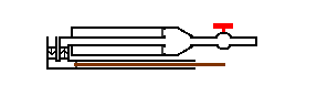
This image of the diagrams "firing"should help more than anything I say:

Image

The first one marked with "1" is (correct me if I'm wrong) what I believe is going on in his diagram. The second on is what I recommend. As you can see, the first one has some bends and at least three major eddies; the second's only got the only two eddies that Supercannon II has. At least I think.
Last edited by Drenchenator on Thu May 15, 2008 10:09 pm, edited 1 time in total.
The Drenchenator, also known as Lt. Col. Drench.

User avatar
Silence
Posts: 3825
Joined: Sun Apr 09, 2006 9:01 pm

Re: Has anyone tried this?

Post by Silence » Thu May 15, 2008 1:19 am

The labeling is a bit off in the diagram he created, but the thin tube in the middle is actually the bladder. The plunger is connected to the bladder and slides inside the case. And instead of the end of the bladder being sealed on, as in a CPS gun, the end is open but the plunger seals against the larger chamber even as it slides. Because the O-ring can be on the outside of the plunger, it should be much easier to make a good seal.

aEx155, the bladder should be cut much shorter before it is filled - it should be about a third of the length of the entire chamber if you want it to expand the whole way. So in your image, the plunger would actually be only a third away from the right side of the case. As it fills, it approaches the other side. :cool:

User avatar
Drenchenator
Posts: 807
Joined: Fri Jun 18, 2004 12:00 pm

Re: Has anyone tried this?

Post by Drenchenator » Thu May 15, 2008 2:45 am

Oh, I thought he was using just a piston that is guided by a tube that also fills it, compressing the air, powering it, blah blah. I didn't realize it had a bladder, making it completely different. You're completely right then. I understand completely now. Mi culpa.
The Drenchenator, also known as Lt. Col. Drench.

aEx155
Posts: 325
Joined: Sun Apr 27, 2008 3:13 am

Re: Has anyone tried this?

Post by aEx155 » Thu May 15, 2008 3:08 am

Oh, I thought he was using just a piston that is guided by a tube that also fills it, compressing the air, powering it, blah blah. Completely different. You're completely right then. I understand completely now. Mi culpa.
Actually, Drenchanator is right with what he said the first time. It would be like Ben's Supercannon (I, not II), but it would have a doughnut-plunger and a inlet instead of a cleanout cap. I really sorta ditched the whole "LRT sliding hose barb thing" idea because it made it too complicated. While this is still complicated, I believe it would be simpler than making a sliding hose barb and the really thing pipe. (Plus, the pipe would impede flow, because it would have to be smaller than 3/8" to fit in the barb)

Image

That was what I was thinking. Rather than having a mess of check valves below the PC, I put the check valves behind it. That was the whole idea that started this. (Now do you know why I wanted to know if the LRT would push water out both ends?) The picture's pretty small, but ti's the same thing as before, just with stuff added so it would make more sense.
Last edited by aEx155 on Sun May 18, 2008 3:14 pm, edited 1 time in total.

User avatar
Drenchenator
Posts: 807
Joined: Fri Jun 18, 2004 12:00 pm

Re: Has anyone tried this?

Post by Drenchenator » Thu May 15, 2008 3:22 am

Wow, that diagram is exactly what I thought you were thinking about.

I guess it's possible if you get the right sized parts. The big problem is going to be getting a piston seal that seals at the center, but if you get it with a slightly larger hole, you might be about to get O-rings that could seal around the guide/filling rod. Just an idea.
The Drenchenator, also known as Lt. Col. Drench.

aEx155
Posts: 325
Joined: Sun Apr 27, 2008 3:13 am

Re: Has anyone tried this?

Post by aEx155 » Thu May 15, 2008 3:29 am

Well, it just seems like a better way to do things. Like I said, it's like Ben's Supercannon I with a piston, so it's a combination of the two Supercannons. I said it reminded me of the Flash Flood because I wanted it to be worn on the bottom of your arm, which is why wanted to make things more compact.

User avatar
sneakycookie
Posts: 32
Joined: Wed May 07, 2008 10:48 pm

Re: Has anyone tried this?

Post by sneakycookie » Thu May 15, 2008 5:14 am

Picture is gone. I didnt get to see it!
Add me on xfire, "sneakiecookie"

aEx155
Posts: 325
Joined: Sun Apr 27, 2008 3:13 am

Re: Has anyone tried this?

Post by aEx155 » Thu May 15, 2008 9:50 pm

sneakycookie wrote:Picture is gone. I didnt get to see it!
What do you mean? The pictures show up clearly. If you want, I can give you direct links to the pictures; otherwise, I don't see why you can't see the pictures.

User avatar
CROC
Posts: 302
Joined: Fri Mar 31, 2006 10:03 pm

Re: Has anyone tried this?

Post by CROC » Fri May 16, 2008 3:23 pm

If you go and click on the PVC drawing thing, and delete to /Posted/, you will be able to see it
-Croc
It's been a while guys, and its good to be back

User avatar
Silence
Posts: 3825
Joined: Sun Apr 09, 2006 9:01 pm

Re: Has anyone tried this?

Post by Silence » Sun May 18, 2008 12:59 am

Refresh the page with no cache if you can't see it. It might turn up then.

Sorry, I guess I was wrong after all :p . Although if you are interested in a sliding barb, I would encourage you to use the design I thought you were using. It would be a lot easier to create a seal and you wouldn't restrict flow if you did that.

aEx155
Posts: 325
Joined: Sun Apr 27, 2008 3:13 am

Re: Has anyone tried this?

Post by aEx155 » Sun May 18, 2008 6:20 am

Well, if 3/8" is the size barb, making it smaller would seem to definitely make it smaller:

Image

If 1/2" is bad, imagine smaller than 3/8"...

User avatar
CROC
Posts: 302
Joined: Fri Mar 31, 2006 10:03 pm

Re: Has anyone tried this?

Post by CROC » Sun May 18, 2008 12:41 pm

To fix the image problem at the start of the topic, put /posted/ in between your profile name and your image name. That's why they say it was deleted or moved.
-Croc
It's been a while guys, and its good to be back

User avatar
Silence
Posts: 3825
Joined: Sun Apr 09, 2006 9:01 pm

Re: Has anyone tried this?

Post by Silence » Sun May 18, 2008 3:33 pm

aEx155, the rubber tube stretches around the barb. Then you use a metal hose clamp to hold the rubber onto the barb. You'll know it when you see it.

The reason barbs constrict flow more than normal is the measurement for the barb part (not the threaded connection) is for the outer diameter, not the inner diameter (which is what other fittings use). Thus, its inner diameter is actually smaller than you'd expect.

Also, Schedule 40 PVC is larger than the actual measurement says it is, up to about 3". So 1/2" PVC actually has an ID of about 5/8" and an OD of about 7/8". A 1/2" hose barb would have an OD of about 1/2" and an ID of 3/8" or less.

aEx155
Posts: 325
Joined: Sun Apr 27, 2008 3:13 am

Re: Has anyone tried this?

Post by aEx155 » Sun May 18, 2008 9:02 pm

SilentGuy wrote:aEx155, the rubber tube stretches around the barb. Then you use a metal hose clamp to hold the rubber onto the barb. You'll know it when you see it.
I know what a tubing barb and a hose clamp are. I was just confused on their measurements. In the picture, the black part labeled "Tubing Barb, 3/8" represents the part where the LRT would slide over. I just didn't put the barbs. (Are those correct measurements?)
SilentGuy wrote:Also, Schedule 40 PVC is larger than the actual measurement says it is, up to about 3". So 1/2" PVC actually has an ID of about 5/8" and an OD of about 7/8". A 1/2" hose barb would have an OD of about 1/2" and an ID of 3/8" or less.
I know. If you look at the picture I posted, where it says "1/2" PVC ID", the scale says that the picture is 5/8" in diameter for the inside. Using the scale makes it accurate. (Hopefully that's not too confusing...)
SilentGuy wrote:Although if you are interested in a sliding barb, I would encourage you to use the design I thought you were using. It would be a lot easier to create a seal and you wouldn't restrict flow if you did that.
SilentGuy wrote:The reason barbs constrict flow more than normal is the measurement for the barb part (not the threaded connection) is for the outer diameter, not the inner diameter (which is what other fittings use). Thus, its inner diameter is actually smaller than you'd expect.
Are you contradicting yourself here? First you say "you wouldn't restrict flow if you did that" but later you say "The reason barbs constrict flow more than normal". What?
Last edited by Drenchenator on Sun May 18, 2008 9:21 pm, edited 1 time in total.

User avatar
Silence
Posts: 3825
Joined: Sun Apr 09, 2006 9:01 pm

Re: Has anyone tried this?

Post by Silence » Mon May 19, 2008 12:07 am

In your most recent diagram, I'm not sure what the lines depicting the first tube are. I thought it was a barb with the rubber inside it, but that's a silly assumption after all this discussion...that's probably the tube it slides on. Maybe I thought you were using the following design.

"The design I thought you were using" is completely different. In your picture...
Image
...here's what I thought was going on:
  • The narrow tube in the middle is actually the LRT.
  • The plunger has an O-ring on its outer edge, touching the wide tube.
  • The LRT is attached on the right side to a fixed barb.
  • The LRT is attached on the left side to a barb on the plunger.
  • (When empty, the plunger and left barb would be much closer to the nozzle.) As the bladder expands, the entire plunger slides inside the outer tube to the left side.
Now go back and read my post...it should make more sense now. There are actually quite a few advantages to this design:
  • Wider tubing/more flow, because you're not trying to thread a really narrow tube through a small hose barb.
  • A seal that's much easier to create. I can assure you it's a lot easier to work with O-rings on convex surfaces instead of on concave surfaces, for two reasons:
    • You can see what you're doing.
    • It's easier to stretch an O-ring (if it's too small for the convex surface) to get it to fit than to stretch or compress it (if it's too small or large for the concave surface).
Sorry for the confusion. :cool:

Locked