Launchers are one of my fields of speciality, but I tend to make lower bore launchers. I keep on meaning to build a WBL, but I keep on getting dragged away.
An idea for a homemade
-
joannaardway

- Posts: 855
- Joined: Mon Feb 20, 2006 10:04 pm
That location is very long..... Where do you live then? 
Launchers are one of my fields of speciality, but I tend to make lower bore launchers. I keep on meaning to build a WBL, but I keep on getting dragged away.
Launchers are one of my fields of speciality, but I tend to make lower bore launchers. I keep on meaning to build a WBL, but I keep on getting dragged away.
"Over the hills and far away, she prays he will return one day. As sure as the rivers reach the seas, back in his arms again she'll be." - Over the Hills and far away, Gary Moore
"So many people have come and gone, their faces fade as the years go by. Yet I still recall as I wander on, as clear as the sun in the summer sky" - More than a feeling, Boston
"So many people have come and gone, their faces fade as the years go by. Yet I still recall as I wander on, as clear as the sun in the summer sky" - More than a feeling, Boston
-
Silence

- Posts: 3825
- Joined: Sun Apr 09, 2006 9:01 pm
So your new design involves placing the pistons horizontally? That sounds pretty good, but if you can get the resources then perhaps just one or two 4" tubes would be better. Also, you would need a 3/8" pump in order to maximize the power--another reason this wouldn't be that good as a rifle.
That location is pretty long. There's nothing stopping you from using it, but it can get pretty distracting...
I'm pretty sure a design using the horizontal-width plane would be very possible, but mainly only with vinyl tubing for design flexibility. Also, to prevent bulkiness, it might be good with brass tubing or something. Just a thought.
Is brass tubing heavier or lighter than equivalent PVC tubing? My mini APH weighs in just under 5 pounds, yet everybody calls it heavy. Perhaps it's a psychological problem with PVC...
-
CROC

- Posts: 302
- Joined: Fri Mar 31, 2006 10:03 pm
Just make a piston homemade to start. That's what I did, and they're very simple. see my other thread in the homemade sectionI think is probably possible, I have never tryed to make a water gun. I myself have only made massive potato cannons. so if you want any tips on Pressurized Air Cannons i could help you out.
Now, back on topic...
Please disregard my last post, as I just went to home depot, and found some 3/8" OD-1/4" ID LRT (amber, not black). It gets up to about 2", therefore making me need 2 1/2" PVC( I can buy little amounts in at Home Depot). My ball valve would be 1/2" or 3/4", and I would have a fake trigger, as stated in an earlier post, so that my enemy thinks it is double barreled, when they then get pummeled by only one stream
I would have to modify the ball valve's lever to do this though, as only one lever would make them know that it is only single barreled.
-Croc
It's been a while guys, and its good to be back
It's been a while guys, and its good to be back
-
Silence
- Posts: 3825
- Joined: Sun Apr 09, 2006 9:01 pm
That's great! Just remember to think things through completely, since this isn't very traditional a design. Perhaps you can call it a CPH Array Gun or something to give yourself an excuse for inevitably making it bigger than in the game.
I would just go with 3" tubing--it's probably found more readily and thus a bit cheaper. Also, if you ever decide to use larger LRT on top or even inner tubing for now, then there will be more space. And finally, it will allow for more reservoir capacity.
Can you borrow a hole saw? If not, do you have any large drill bits? With the correct sized vinyl tubing, you'd have a lot of flexibility with the design.
Actually, I have a revised theoretical design if you're interested in it--partly possible if you actually can get 2.5" PVC. I'll work on a paint diagram to explain it.
-
CROC
- Posts: 302
- Joined: Fri Mar 31, 2006 10:03 pm
Uhh yea. The LRT is a bit small to colossus right now, as I have 1/4" nipples and such inside, and it is only 3/8" large. Pricewise for the pipe, I'm not sure, but if Home Depot doesn't have any of the 2 1/2" PVC, I will just use 3", as you suggest.
I could use some kind of tubing, but I am unsure how it would get drawn from one side to the other.
The largest size drill bit I have is about 3/8", which is large enough for tubing.
This is my plan:
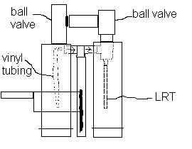
Would this work? Or will I need to revise my plan
I could use some kind of tubing, but I am unsure how it would get drawn from one side to the other.
The largest size drill bit I have is about 3/8", which is large enough for tubing.
This is my plan:
Would this work? Or will I need to revise my plan
Last edited by CROC on Mon Sep 11, 2006 9:14 pm, edited 1 time in total.
-Croc
It's been a while guys, and its good to be back
It's been a while guys, and its good to be back
-
Silence
- Posts: 3825
- Joined: Sun Apr 09, 2006 9:01 pm
Ah, very nice...that pump location is very much what I was going to suggest. You'll see in a while. 
There are only two problems I can see with this: (1) the check valves, even metal ones, would make each tube be very far apart; and (2) the potential volume of the bladder would be as large as the reservoir. That isn't an inherent problem assuming you will fill/pump/fill and then perhaps tap/pump, but it's still a stretch.
Actually, I still suggest using a second ball valve on that piece of tubing in front of the reservoir. That will both give the soaker a fake double barrel and a place to fill it.
The reason I suggested vinyl tubing was to get the water to the back of the pump. Do you have to push, not pull, the pump in your design? I thought about that, but that wouldn't be too useful, IMO. It was just a way to bypass problems with my initial suggestion.
-
13lack-ace
- Posts: 16
- Joined: Sun Aug 20, 2006 9:40 am
Shot gun
Argh, ok this is hard to put. I have a shotgun with ruled up plans in my teams main base. There is one small problem, It looks a bit like your design but you have to cock it in order to put the ammo (pull back a lever and put in ammo then push forward and lock down then fire). I think you want something more as so... It has cartridges?
"A good plan, violently executed now, is better than a perfect plan next week."
''America loves a winner, and will not tolerate a loser, this is why America has never, and will never, lose a war.
''America loves a winner, and will not tolerate a loser, this is why America has never, and will never, lose a war.
-
CROC
- Posts: 302
- Joined: Fri Mar 31, 2006 10:03 pm
I would modify the tee, so that the check valves would fit in, without any problems, and keep the design compact. The pump is pulled, not pushed, and it does not use cartridges, as 13lack ace is thinking. It just opens the ball valve, then you re-pump the LRT chamber, and repeat.
NOTE: I will have to find some adapters from 3/8 to either 3/4 or 1/2 inch, as the nipple adapter is only 1/4"
EDIT: Updated sketch on paint in previous post
No, it does not.It has cartridges?
That's actually a really good idea! Thanks for the suggestion.Actually, I still suggest using a second ball valve on that piece of tubing in front of the reservoir. That will both give the soaker a fake double barrel and a place to fill it.
NOTE: I will have to find some adapters from 3/8 to either 3/4 or 1/2 inch, as the nipple adapter is only 1/4"
EDIT: Updated sketch on paint in previous post
Last edited by CROC on Mon Sep 11, 2006 9:21 pm, edited 1 time in total.
-Croc
It's been a while guys, and its good to be back
It's been a while guys, and its good to be back
-
Silence
- Posts: 3825
- Joined: Sun Apr 09, 2006 9:01 pm
Here's what I was thinking of:
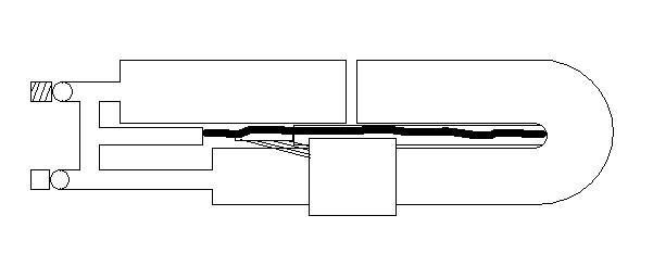
Of course, since metal check valve will likely be too expensive, PVC ones parallel to each other and the soaker would probably be better. The two sides should be as close as possible, with the pump tube hidden in between and in the space underneath; a tube over the reservoir connects with a long piece to the rod. Also, you can try a design like in joannaardway's homemade or like the Displacement Pump if you want.
The tube over the reservoir could actually just be a tee (with a reducer in it for a smaller PVC handle) with the inner rim sanded down for sliding, or it could be 3" PVC. You'll also want to use a tee or just a coupler or something over the pump tube, as that will create a trigger that slides smoothly along it. The new design is as simple as possible I think for the purpose, unlike my original suggestion.
EDIT: Tell me if you can't see where the LRT and check valves are; I forgot to mark them. I'd actually suggest just putting epoxy or something over vinyl tubing (if it would work) and sticking that in a joint; that would be great, especially in locations that don't hold pressure. Tubes going to the back of the pump would have check valves in the middle...
-
CROC
- Posts: 302
- Joined: Fri Mar 31, 2006 10:03 pm
I was thinking that the tube over the resevoir was like the pump handle. The only check valves I'd want would be spring loaded PVC anyways, because I could then pump and shoot at any angle, without water going backwards, to the pump and so on. I wouldn't care if it had a turbulent flow, coming from the nozzle. I am estimating that it iwll get about 10-20x from the LRT, but I'm not sure. The LRT would be covered. In my diagram ^^ the dotted lines are inside the PVC, while solid lines are on the outside.^^
I will probably post instructions on how to build it when I have all the parts, and am starting to build it (I still need to amass funds to get the right sized pvc and so on,but when I get there, or when I get paid by my dad for working at his company for ~21hours, I can start. I will also start by just describing it, as I lack a digital camera right now, but when I get one, I will post pics)
-Croc
It's been a while guys, and its good to be back
It's been a while guys, and its good to be back
-
Silence
- Posts: 3825
- Joined: Sun Apr 09, 2006 9:01 pm
The displacement pump is definitely one of my earlier ideas. Its entire purpose was to help in designs like this that call for water flow from the front. Oh, and you can have just one tube attaching to the front of the pump tube with both check valves coming off of that.
The tube over the reservoir will be part of the pump handle--I just suggested a tee or a coupler or something else 2.5" with the inner rim removed, as its fit would be very tight and smooth--sand the entire inside if you want. I just suggest that a connection between the pump rod and the sliding part over the reservoir be very long, such that the sliding part is farther back and fairly level with its location on the ACP Array Gun and with the actual pump tube.
The metal check valves I suggested also use springs (I think), as do the PVC ones; and the ball valves are just like regular ones. However, the metal check valves are much, much shorter than are the PVC ones, they can also handle greater pressures, but you won't notice that. In my picture, there actually is space for long PVC ones (I think; metal ones would definitely work, but they're more expensive) as long as the center tube is on a 3rd dimension, such as below the main gun and near the level of the pump.
-
CROC
- Posts: 302
- Joined: Fri Mar 31, 2006 10:03 pm
No offence, but I can see why they all shunned it. How would the water get to the second check valve?
I want the pump to slide relatively easy, as I am not really wanting a hard time with my first homemade pump that would need to withstand pressure (I will need to buy primer and cement too, so bear with me if I get insufficient funds half way through the project) I'm hoping to get this done by the next water gun season, and to help mr.dude with his too, as I live close to him (ish). I have some wierd designs for modding the check valve and tee so that my design stays compact, like chopping off most of the arms of the T, making it shorter, and cutting down parts of the check valve that are not necessary, to make it as compact as possible. I couldn't find any of those little metal grip things like drenchenator has on his homemade, so I just put 2 tie wraps around the nipple and tightened them until I could not tighten them anymore. Will this work, or should I go searching for those little metal clamps? I will probably drill an exhaust port in the side with the PC, at the end so that it doesn't create pressure in the PC, which, as read elsewhere on the site, will distort something. It's good to know that you and I are somewhat on the same page in the designs though, because then if there are problems with one, there is always other parts from the other design to use, and it wouldn't require much changing of the gun. I am going to be eventually making a trigger mech which is auto close, but I will need to think up the opener part( I'm thinking that I could use some left over 2.5" or 3", depending on what I get and make a groove for the pump-pump handle connector. Then I could probably use a Nerf style sliding trigger, connected to the modded ball valve (Still need to find out how the hell I'm gonna do that though) and, when pulled, stretches the spring, making it snap back when not in use.
I can find 4" tees/couplers for that, making my possible resevoir width up to !3 inches!tee or a coupler or something else 2.5" with the inner rim removed, as its fit would be very tight and smooth
I want the pump to slide relatively easy, as I am not really wanting a hard time with my first homemade pump that would need to withstand pressure (I will need to buy primer and cement too, so bear with me if I get insufficient funds half way through the project) I'm hoping to get this done by the next water gun season, and to help mr.dude with his too, as I live close to him (ish). I have some wierd designs for modding the check valve and tee so that my design stays compact, like chopping off most of the arms of the T, making it shorter, and cutting down parts of the check valve that are not necessary, to make it as compact as possible. I couldn't find any of those little metal grip things like drenchenator has on his homemade, so I just put 2 tie wraps around the nipple and tightened them until I could not tighten them anymore. Will this work, or should I go searching for those little metal clamps? I will probably drill an exhaust port in the side with the PC, at the end so that it doesn't create pressure in the PC, which, as read elsewhere on the site, will distort something. It's good to know that you and I are somewhat on the same page in the designs though, because then if there are problems with one, there is always other parts from the other design to use, and it wouldn't require much changing of the gun. I am going to be eventually making a trigger mech which is auto close, but I will need to think up the opener part( I'm thinking that I could use some left over 2.5" or 3", depending on what I get and make a groove for the pump-pump handle connector. Then I could probably use a Nerf style sliding trigger, connected to the modded ball valve (Still need to find out how the hell I'm gonna do that though) and, when pulled, stretches the spring, making it snap back when not in use.
-Croc
It's been a while guys, and its good to be back
It's been a while guys, and its good to be back
-
DX

- Posts: 1780
- Joined: Wed Feb 04, 2004 1:00 pm
Can we please end the absolute that metal is more expensive? It is only more expensive in CHAIN STORES. In local stores, they can be up to $10 cheaper than the same size PVC valves. I've dropped all the other stuff because it has been proven that there's little operational difference when a torque arm is made. The price thing is just annoying because I can show you plenty of examples to the contrary. I now buy a good 99% of my homemade parts locally [everything but check valves] because the prices are superior, especially with metal ball valves and large pipe fittings.
Mess With the Best, Get Soaked Like the Rest!
2004 Red Sox - World Series Champions
2007 Red Sox - World Series Champions!
2004 Red Sox - World Series Champions
2007 Red Sox - World Series Champions!
-
Silence
- Posts: 3825
- Joined: Sun Apr 09, 2006 9:01 pm
Whatever...here at least, no place has metal too cheap. It is Virginia, of course, and if doesn't matter how commercialized my city is. Seriously. I need to migrate north.
There's nothing wrong with cutting and sanding out the inside of a tee or a coupler, and you can check out the Aqualabs 3.2 design if you want. A similar method would also work well for the trigger. Just a little bit of sanding with a coarse grain will loosen all the joints up sufficiently, although that's something I would check before gluing.
I would go with the pump design here at SSC. It's tried and tested (alas, not by me--I did things the hard way), and there's no reason it shouldn't work. Of course, having a piece that moves the pump handle-attachment-piece-thingy back isn't really necessary.
@ more experienced people: How well does PVC bond with epoxy? If it bonds well, then you could easily just shove 1/2" pressure-rated flexible piping into the tee and pump with a bit of glue for the perfect seal. As long as the two check valves lead to a center piece at an angle (a simple tee wouldn't work, though, if you want symmetry), the check valves can be any length you desire.
The torque arm for the ball valve shouldn't be too hard, so I wouldn't worry about it yet.
-
CROC
- Posts: 302
- Joined: Fri Mar 31, 2006 10:03 pm
You're right about PVC being alot cheaper than metal, as 1/2" PVC (please note I'm stating prices in Canadian funds, so don't quote me on prices if you live in the US) costs about $5-6 for 10 feet, while copper is about $10 for 1/2", 10 ft long pieces.
When I go looking, I will proably buy the most compact spring loaded check valve. I will go in to more depth tomorrow
When I go looking, I will proably buy the most compact spring loaded check valve. I will go in to more depth tomorrow
-Croc
It's been a while guys, and its good to be back
It's been a while guys, and its good to be back