New Linear Flow Valve

Homemade water gun threads that are notable.
User avatar
Drenchenator
Posts: 807
Joined: Fri Jun 18, 2004 12:00 pm

New Linear Flow Valve

Post by Drenchenator » Wed Sep 05, 2007 1:20 pm

Ben wrote:Drenchenator has been working on a type of pull valve with mixed results. It's not at all like what I described and is a completely new valve design. It needs some bugs worked out definitely, but right now it is functional. I'll leave posting about it to him.

The valve that Ben described is truly a completely new kind of valve. I don't have a good name for it; Until I do, let's call it a "new linear flow valve." I wasn't planning on posting it until my CPS homemade was done, but it works and Ben "burst the bubble."

A few people have tried to build homemade pull valves with limited results. Ideally, a valve should provide linear and then laminar flow; a pull valve does not. I built this out of a desire for a "homemade linear flow valve."

Image

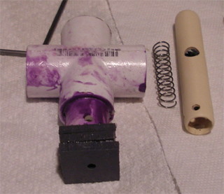
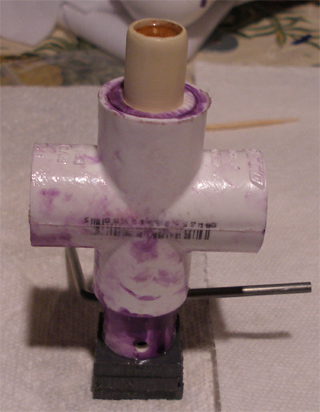
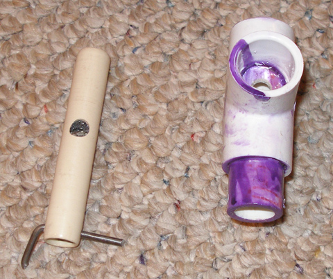
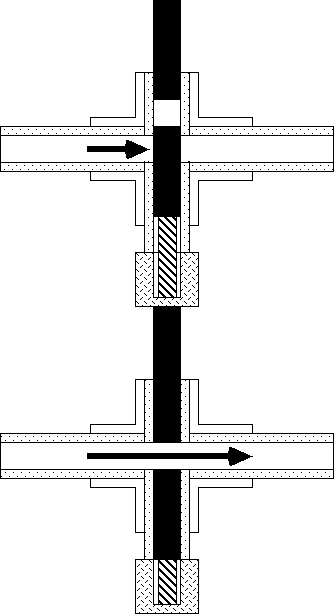
The valve works like a ball valve; however, instead of a ball with a hole in it, a cylinder with a hole is used. The cross contains a section of 1/2" PVC to house the cylinder.
Image

The bottom section houses a spring to push the cylinder out of alignment when the valve is not activated. I have a video showing the valve's assembly and function but it is too large (~60 MB) to post.

This valve was having "mixed results." Though it closes beautifully, I was unable to finish the trigger system to attach it to my homemade. I just ran out of time to complete it over the summer again. Secondly, my bad homemade test cylinder does leak. I used foam backer rod to fill some 1/2" CPVC to make it. Without a lathe, my sanding could only approximate the correct size. Ben recommended that I use 5/8" rubber rod for the cylinder and I have to agree. 1/2" PVC has a diameter of .622", 5/8" rubber rod has a diameter of .625". Plus, most seals are made of rubber anyway.

Edit: Changed tee to cross.

The valve animation
Image

More pictures

Image

Image
Last edited by Drenchenator on Thu Sep 06, 2007 10:39 pm, edited 1 time in total.
The Drenchenator, also known as Lt. Col. Drench.

User avatar
Silence
Posts: 3825
Joined: Sun Apr 09, 2006 9:01 pm

Post by Silence » Wed Sep 05, 2007 10:37 pm

I like the prototype quite a bit. Sorry for ruining your plans...your homemade naturally shows a lot of potential.

I presume the ports are the center and one of the side legs...but is that necessarily linear? Regardless, I believe going for linear design isn't exactly the best choice if it sacrifices flow. Anyway, I'm just wondering, why is the hole in your cylinder so small? Does it have to do with seal sizes?

Alternatively, you could just have the plunger in the center leg and have water flow straight through the tee. That would definitely require machining though, even if you were to use a non-cylindrical plunger (like a sluice gate).

User avatar
Drenchenator
Posts: 807
Joined: Fri Jun 18, 2004 12:00 pm

Post by Drenchenator » Wed Sep 05, 2007 11:34 pm

I presume the ports are the center and one of the side legs...but is that necessarily linear?
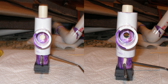
No, the ports are just the open ends of the cross. I do not have a picture of the valve installed in the gun, but I can describe how it works. When closed, the cylinder is pushed up a half inch by a spring. When pulled down, the hole in the cylinder aligns with the hole in the cross, allowing a straight path for the fluid to flow.
Anyway, I'm just wondering, why is the hole in your cylinder so small? Does it have to do with seal sizes?
The hole was small because this valve was more or less a test for a better valve. While building it, I just grabbed a 5/16" drill bit and drilled away. This prototype was supposed to be proof-of-concept for an improved valve to work out bugs prematurely. As I said before, the cylinder ideally should be a 5/8" rubber rod. I think that 5/8" hole could work only if the cylinder was divided into 2: a "plug" and a movable cylinder. Instead of aligning a hole, the movable cylinder is just retracted to open up the hole in the cross. Simple enough.

I probably should make an animation of how this valve works. It works like a ball valve; a hole is aligned with another hole to offer flow.
Last edited by Drenchenator on Thu Sep 06, 2007 10:46 pm, edited 1 time in total.
The Drenchenator, also known as Lt. Col. Drench.

User avatar
Silence
Posts: 3825
Joined: Sun Apr 09, 2006 9:01 pm

Post by Silence » Thu Sep 06, 2007 12:27 am

Right, I was assuming instead of holes aligning, the entire rod moved out of the way.

Anyway, I'll look forward to your animation, although even a simple drawing scanned in might suffice. My curiosity is piqued...(I think) I know where you're going with this, but it looks more like the water goes through the center and a side and not straight through.

User avatar
isoaker_com
Posts: 458
Joined: Wed Oct 27, 2004 12:00 pm

Post by isoaker_com » Thu Sep 06, 2007 1:27 am

While a promising device as a homemade valve for water blasters, the valve design, itself, looks like a gate-valve, but using a cylinder when a cylindrical piece really is not necessarily needed. A flat gate that's water tight with a hole cut in it could work as well if not better than a cylinder. Either that or a reverse gate that plugs the flow as opposed to opens a hole is another option. i.e. Image

Optimally, if you wish to achieve linear flow, the hole in the valve should be equal in width to the tubing on both sides of the valve, but that's pretty much a given. :p

Promising progress, for sure, though!

:cool:
:: Leave NO one dry! :: iSoaker.com / iSoaker.net ::

User avatar
Drenchenator
Posts: 807
Joined: Fri Jun 18, 2004 12:00 pm

Post by Drenchenator » Thu Sep 06, 2007 2:25 am

Is this linear or not?

Image

The fluid can flow straight through without interference: the definition of laminar flow.

Edit: the transparency in the GIF didn't seem to work. Oh well, I can barely notice it on my laptop.
Last edited by Drenchenator on Thu Sep 06, 2007 11:28 am, edited 1 time in total.
The Drenchenator, also known as Lt. Col. Drench.

User avatar
Silence
Posts: 3825
Joined: Sun Apr 09, 2006 9:01 pm

Post by Silence » Thu Sep 06, 2007 8:27 pm

Oh, so it's a cross, not a tee...sorry, I misinterpreted the entire layout. It's hard to tell it's a cross from the pictures, too.

Sounds like a great design, and it seems flexible enough to be used in various setups. Good luck with your homemade too. :cool:

I still have my doubts about necessitating linear flow, though...for example, unless you have a tube going between the holes in the cylinder, I can promise you'll just be creating more turbulence.

User avatar
Drenchenator
Posts: 807
Joined: Fri Jun 18, 2004 12:00 pm

Post by Drenchenator » Thu Sep 06, 2007 10:33 pm

Oh, so it's a cross, not a tee...sorry, I misinterpreted the entire layout. It's hard to tell it's a cross from the pictures, too.

That was my fault; I didn't realize which pictures I used until now. Plus, I accidently said "tee" instead of "cross." The terminology is confusing sometimes I guess since a tee is in fact a capital T and a cross a lower-case t.

Image

Image
I still have my doubts about necessitating linear flow, though...for example, unless you have a tube going between the holes in the cylinder, I can promise you'll just be creating more turbulence.
A good drill bit and file can do wonders. I sanded the cylinder completely smooth using a sanding block. With the right experience and tools, it is possible to sand it perfectly smooth.

Higher flow does create more laminar flow. However, this valve was designed to be used in my CPS homemade; its size matters. It needs to be small. It got 40x during testing last summer, so the flow is fine.

I am hoping to eventually make a much larger version to see how it would work though.
Last edited by Drenchenator on Thu Sep 06, 2007 10:48 pm, edited 1 time in total.
The Drenchenator, also known as Lt. Col. Drench.

User avatar
Silence
Posts: 3825
Joined: Sun Apr 09, 2006 9:01 pm

Post by Silence » Thu Sep 06, 2007 11:05 pm

My concern with turbulence lies more with the fact that water crosses through a hollow tube than with the fact that there might be rough surfaces or burrs. Once the flow passes into the cylinder, eddies trapped inside will add turbulence, and a similar effect will occur if the hole sizes are smaller than the barrel's bore (which you've said you'll fix). :cool:

At the very least, you must admit a ball valve generates much less turbulence. However, the nozzles and all will generate turbulence anyway, so it's probably not too big an issue. The valve should provide lots of flow, as you've said.

User avatar
Drenchenator
Posts: 807
Joined: Fri Jun 18, 2004 12:00 pm

Post by Drenchenator » Thu Sep 06, 2007 11:13 pm

My concern with turbulence lies more with the fact that water crosses through a hollow tube than with the fact that there might be rough surfaces or burrs. Once the flow passes into the cylinder, eddies trapped inside will add turbulence, and a similar effect will occur if the hole sizes are smaller than the barrel's bore (which you've said you'll fix).
The cylinder is not hollow. I filled in with foam backer rod and glued the rod with epoxy. It still leaks though. In the end, a 5/8" rubber rod should (and was planned to) be used in this valve. If I drill a hole through it and sand it well, no turbulence is created. Remember, the CPVC cylinder was for testing; a solid rubber rod will not only seal better but also perform better.
At the very least, you must admit a ball valve generates much less turbulence. However, the nozzles and all will generate turbulence anyway, so it's probably not too big an issue. The valve should provide lots of flow, as you've said.
Of course a ball valve has less turbulence. It's made in a factory, not in my basement like this one.
Last edited by Drenchenator on Thu Sep 06, 2007 11:24 pm, edited 1 time in total.
The Drenchenator, also known as Lt. Col. Drench.

User avatar
Silence
Posts: 3825
Joined: Sun Apr 09, 2006 9:01 pm

Post by Silence » Fri Sep 07, 2007 8:49 pm

I should have reread the first post after seeing the other pictures...the FBR part makes sense now. I didn't realize what it did earlier. (I should have, though...you said "cylinder", not "tube".)

I no longer have severe doubts about the turbulence either...I don't think it's so much a matter of machining as it is of the design. And if you do have filler for the cylinder, that's all the better.

Actually, I'm thinking a design like this is actually better than one in which the cylinder retracts completely and lets water pass below. This system should have much less turbulence, and plenty of flow if a valve can be made well and width large holes in the cylinder.

User avatar
Drenchenator
Posts: 807
Joined: Fri Jun 18, 2004 12:00 pm

Post by Drenchenator » Fri Sep 07, 2007 9:39 pm

Actually, I'm thinking a design like this is actually better than one in which the cylinder retracts completely and lets water pass below. This system should have much less turbulence, and plenty of flow if a valve can be made well and width large holes in the cylinder.
That is exactly what I though when I though of this. I designed it because I wanted a linear flow valve like a ball valve. The insight was changing the ball to a cylinder. A cylinder simply works better with a linear compression spring.

In all, the valve should be very easy to make. When I get time (probably during Winter Break), I will build an improved version with the 5/8" rubber rod, which should solve the seal and sanding issues.
The Drenchenator, also known as Lt. Col. Drench.

User avatar
SSCBen
Posts: 6449
Joined: Sat Mar 22, 2003 1:00 pm

Post by SSCBen » Fri Sep 07, 2007 11:22 pm

This post doesn't have anything to do with Drenchenator's valve. It's just expanding on what iSoaker said. I knew what gate valves were, but I never checked out McMaster-Carr's selection until his comment.

McMaster-Carr has "Quick-Acting PVC Gate Valves" in 1 1/2 inch sizes that should work well (part number 46065K81). These appear to open with a lever that pulls down. The only problem is that they are rated at 75 PSI, which removes very high pressures from the design. Then again, that rating is at 120 degrees Fahrenheit and I would imagine the rating for 70 degrees would be much more reasonable. These would probably work well in a water gun if you modify them to use a trigger. ;)

Edit: Based upon the temperature derating of PVC, this gate valve should be rated at 187.5 PSI at 70 degrees.
Last edited by SSCBen on Mon Sep 10, 2007 3:25 am, edited 1 time in total.

User avatar
Specter
Posts: 474
Joined: Sun May 13, 2007 4:57 pm

Post by Specter » Mon Sep 10, 2007 3:05 am

thats neat. its interesting to see how some of us here are developing homemade valves, for example the homemade check valve WaterWolf made.

It seems easier to operate than a ball valve. Is it easier and does it work as well as a ball valve?
It seems simple enough that anyone can build it if you give good instructions, because the PVC parts you used are very cheap. I don't know how much the rubber rod you will be using costs so can you give some info on that, thanks. Again, hope your improved version works well, and possibly better.
My "arsenal": Customizable APH, Storm 600 pistol (still haven't finished fixing this), launcher- Model:AB1.0(Decommissioned), AB1.5, soon AB 1.1(2"rebuild) maybe ill get something else in the future
My site Image My website/forum is back up and running, for the most part after it having been deleted in october

User avatar
Drenchenator
Posts: 807
Joined: Fri Jun 18, 2004 12:00 pm

Post by Drenchenator » Mon Sep 10, 2007 4:14 am

Is it easier and does it work as well as a ball valve?
It opens very easily. One single push opens it manually. This valve was designed to be used in a triggered gun, so a pull downwards also opens the valve. To complete my CPS homemade, I have to figure out how to do that using the pull of the trigger.

This valve should ideally work as well as a ball valve, but as I said this prototype leaks out of the non-machined cylinder. The rubber rod will fix that problem.
I don't know how much the rubber rod you will be using costs so can you give some info on that, thanks.
My local Lowes doesn't stock rubber rod. On McMaster a 6" length of 5/8" diameter medium soft rubber rod is a costly $9.13. Nonetheless, it is well worth it if I can finish my CPS gun's trigger system with this valve.
thats neat. its interesting to see how some of us here are developing homemade valves, for example the homemade check valve WaterWolf made.
Thanks. I am glad that builders are now advancing the undeveloped field of homemade valves for Super Soakers.
The Drenchenator, also known as Lt. Col. Drench.

Post Reply